Probe & Sensor Wiring
Introduction
Veeder-Root has specific requirements for all Automatic Tank Gauge (ATG), probe, sensor and Pressurized Line Leak Detection (PLLD) transducer wiring – this is to maintain intrinsic safety as well as reduce electrical noise interference. This notification will provide a brief introduction into Veeder-Root’s probe and sensor wiring requirements. This should be used in conjunction with local, state and federal electrical codes.
Basic Wiring & Installation Requirements
The following are Veeder-Root’s field wiring requirements:
- All probes and sensors must use two-wire shielded cable.*
- Use a single continuous length of shielded cable with no splices to ensure optimum signal strength.
- All shielded cable runs must be less than 1000 feet.
- An epoxy pack must be used for all wiring splices in the field.
- Weatherproof junction boxes are required for all conduit runs to the monitoring locations (e.g., STP sump or dispenser pan).
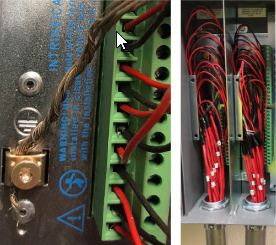
- All shields must be grounded at the console, cut-off in the field.
- When exiting the console, shielded cable must be run through rigid conduit.
- Shielded cable should be rated between 14 to 18 AWG stranded copper wire and must be rated less than 100 picofarads per foot.**
* When installing a three-wire sensor, use a three-wire shielded cable.
** Refer to the TLS-450PLUS Site Prep and Installation Manual (577014-073) for wiring examples.
ATG Installation & Grounding
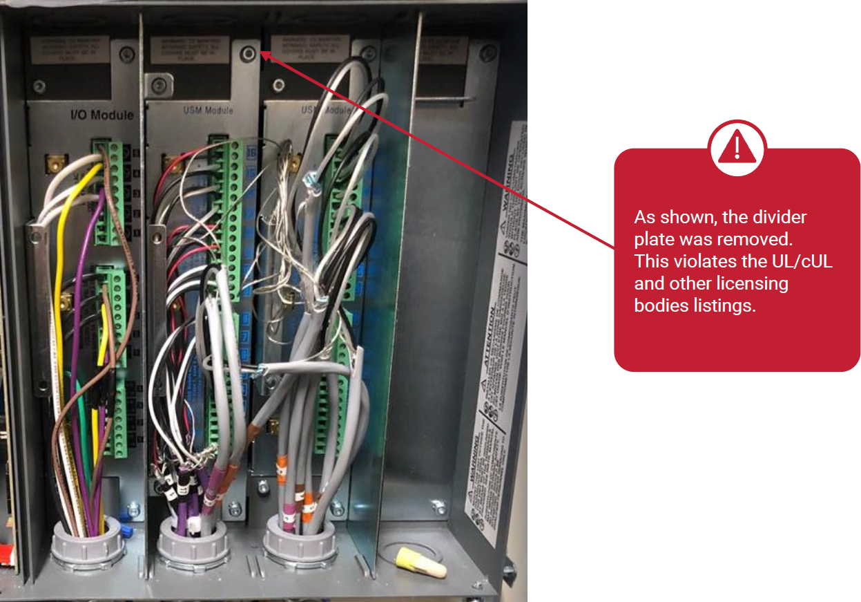
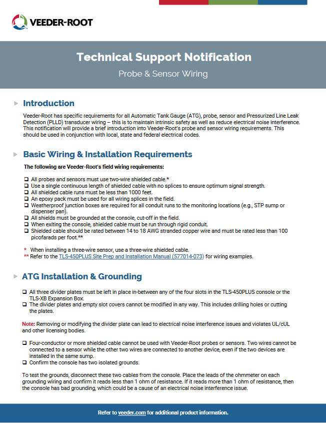
- All three divider plates must be left in place in-between any of the four slots in the TLS-450PLUS console or the TLS-XB Expansion Box.
- The divider plates and empty slot covers cannot be modified in any way. This includes drilling holes or cutting the plates.
Note: Removing or modifying the divider plate can lead to electrical noise interference issues and violates UL/cUL and other licensing bodies.
- Four-conductor or more shielded cable cannot be used with Veeder-Root probes or sensors. Two wires cannot be connected to a sensor while the other two wires are connected to another device, even if the two devices are installed in the same sump.
- Confirm the console has two isolated grounds.
To test the grounds, disconnect these two cables from the console. Place the leads of the ohmmeter on each grounding wiring and confirm it reads less than 1 ohm of resistance. If it reads more than 1 ohm of resistance, then the console has bad grounding, which could be a cause of an electrical noise interference issue.
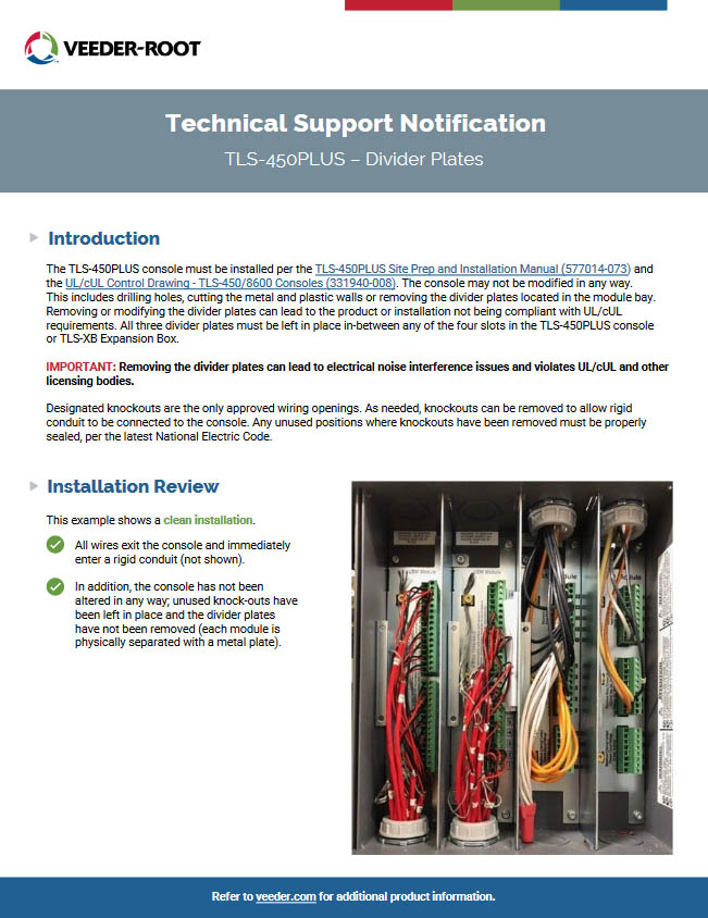
 Installation Review
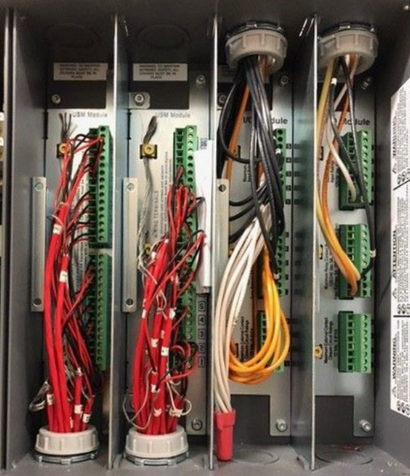
This example shows a clean installation.
✅ One pair of two-conductor shielded cable is used per device.
✅ All shields are grounded at the console.
✅ All shielded cable is run through a rigid conduit.
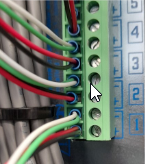 This example shows an incorrect installation.
❌ The field wiring does not meet Veeder-Root, UL/cUL and other licensing bodies’ wiring requirements. This site is using four-conductor shielded cable. (Shields are not shown).
As mentioned before, two-conductor shielded cable is required for all probes and sensors.
Further Information
- Please feel free to contact us with any further questions about this notification at 1-800-451-4021 or Email Us
- Learn more about intrinsic safety and wiring requirements in the TLS-450PLUS Site Prep and Installation Manual (577014-073) and by viewing the UL/cUL Control Drawing – TLS-450/8600 Consoles (331940-008).
DOWNLOAD THE TSN HERE!
LOOKING FOR VEEDER-ROOT SYSTEMS & PARTS?
Well look no further – click on the Veeder-Root logo below to visit our web store, where we have hundreds of the most popular Veeder-Root items ready to buy in our webstore and if you can’t find it there, please feel free to contact us at 1-800-451-4021 or Email Us !!
![]()


 for more product installation and preparation videos