Overview
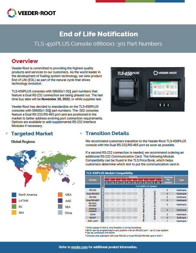
Veeder-Root is committed to providing the highest quality products and services to our customers. As the world leader in the development of fueling system technology, we view product End of Life (EOL) as part of the natural cycle that drives technology evolution.
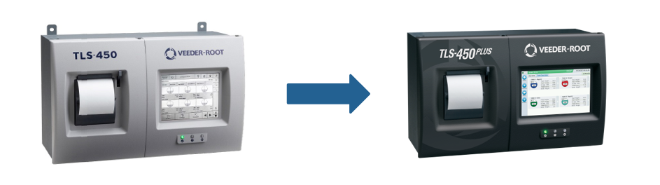
TLS-450PLUS consoles with 08600×1-301 part numbers that feature a Dual RS-232 connection are being phased out. The last time buy date will be November 30, 2022, or while supplies last.
Veeder-Root has decided to standardize on the TLS-450PLUS consoles with 08600×1-302 part numbers. The -302 consoles feature a Dual RS-232/RS-485 port and are positioned in the market to better address evolving port connection requirements. Options are available to add supplemental RS-232 Interface Modules if necessary.
Transition Details
We recommend customers transition to the Veeder-Root TLS-450PLUS console with the Dual RS-232/RS-485 port as soon as possible.
If a second RS-232 connection is needed, we recommend ordering an additional RS-232 Communication Card. The following Module Compatibility can be found in the TLS Price Book, which helps customers determine which slot to put the communication card in.
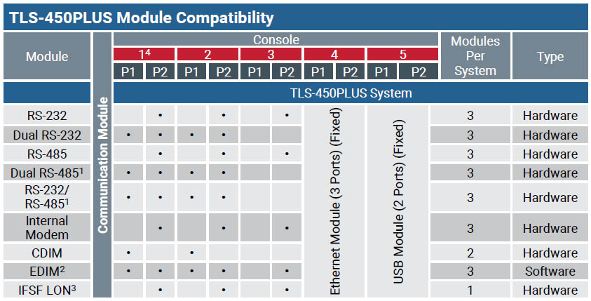 1 When placed in Slot 3, only Position 2 will be functional
2 EDIM can be programmed in any position with an RS-232 port – up to 3 per system
3 Can be combined with EDIM
4 Console ship standard with dual RS-232 or Dual RS-232/RS-485 card in Slot 1
Schedule for TLS-450PLUS Console 08600×1-301 Part Numbers
| End of Life Product Details | ||||
| Platform | Platform Details | Region | End of Life Notification Date | Last Time Buy Date |
| TLS-450PLUS | TLS-450PLUS Console 08600×1-301 Part Numbers | Global | June 13, 2022 | November 30, 2022 |
Impacted Equipment
| End of Life Product Details | ||
| Product Type | Description | Part Number |
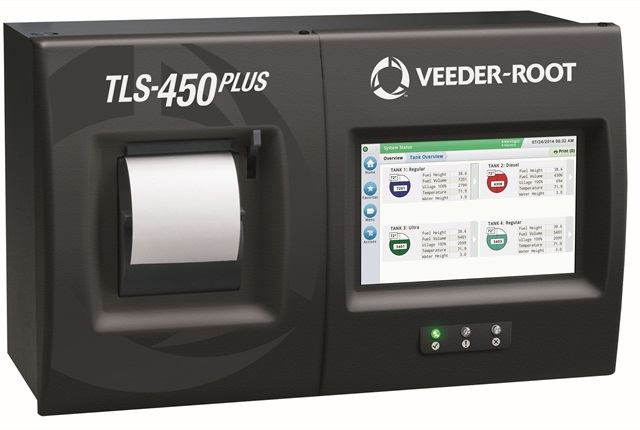
| TLS-450PLUS | TLS-450PLUS Console with 8” WVGA Color Touch Screen Display, Printer, 3 Ethernet and Dual USB/Expansion, Dual RS-232, UL/cUL | 0860091-301 |
| TLS-450PLUS | TLS-450PLUS Console with 8” WVGA Color Touch Screen Display, Printer, 3 Ethernet and Dual USB/Expansion, Dual RS-232, ATEX | 0860061-301 |
| TLS-450PLUS | TLS-450PLUS Console with 8” WVGA Color Touch Screen Display, Printer, 3 Ethernet and Dual USB/Expansion, Dual RS-232, IECEx | 0860011-301 |
Product Transition Information
|
|
|||||||||||||||||||||||||||||||||||||||
CLICK HERE to See the End Of Life Notification from Veeder-Root
LOOKING FOR VEEDER-ROOT SYSTEMS & PARTS?
Well look no further – click on the Veeder-Root logo below to visit our web store, where we have hundreds of the most popular Veeder-Root items ready to buy in our webstore and if you can’t find it there, please contact us!
![]()
If you have any questions about TLS450 or would like to receive a quote for TLS450 Series or any other Veeder-Root system and/or parts , please feel free to contact us at 1-800-451-4021 or Email Us !!


 for more product installation and preparation videos